

")
")
Kaman K-1200 K-Max - History and technical description
Charles Huron Kaman (1919-2011), whose family members and friends used to call "Charlie", has been one of the most important American rotary-wing pioneers.
Already as a young boy he dabbled in building model airplanes dreaming to become an airplane pilot, but he was prevented from doing so because of a hearing problem. Despite that nasty surprise he was not discouraged, he finished compulsory schools and thereafter in 1940 obtained a degree magna cum laude in aeronautical engineering at the Catholic University of America in Washington D.C. That same year he was hired as an aerodynamic engineer by Hamilton Standard Division (HSD) of East Hartford (Connecticut), at the time the largest manufacturer of propellers for the aviation industry.
A very talented character in his spare time he developed a calculator to perform aerodynamic calculations known as the Aerodynamic calculator which was used for many years until the advent of modern computers.
Charles H. Kaman immediately understood that the helicopter offered new and interesting potentials and decided to deepen his technical knowledges by preparing in his spare time a thesis which he then submitted to the Institute of Aeronautical Sciences.
Thanks to his deep interest in the rotary-wing, at that time in its early stage of development, he obtained permission to observe from close the test flights of the experimental helicopter Vought-Sikorsky VS-300 developed by Igor I. Sikorsky for which he had made aerodynamic calculations.
When HSD started to collaborate in the development of the first mass-produced Sikorsky helicopters, the young engineer was appointed as manager of a new aerodynamic department.
At that time helicopters were unstable, the force required to operate the controls was considerable and the performance rather limited. Vibrations coming from the rotor made flying difficult as well as exhausting.
Charles H. Kaman decided to solve these problems developping the idea of the servo-flap, a rotor control mechanism that he believed would make the aircraft more stable and easier to fly.
Several inventors before him had tested, with various success, this original control system. In Italy engineer Corradino D'Ascanio with his D'AT 3 model with two coaxial counter-rotating rotors in October 1930 set the first records of distance, duration and altitude.
In order to test his idea Charles H. Kaman decided to assemble a test bench using the parts of a Pontiac car and the back of a Dodge truck purchased for 50 dollars. Like other suppliers, the owner of the sawmill where the young engineer purchased spruce planks for 1.75 USD was also quite skeptical that they would have been used for a new helicopter model.
")
Given the difficulties in finding some of the material due to the ongoing conflict, Charles H. Kaman, on the advice of some of his acquaintances, founded Kaman Aircraft Laboratory. Thanks to a special permission obtained from the Army, he got everything he needed and immediately set to work in the garage and basement of his mother's house in West Hartfort to manufacture the first rotor blades.
After successfully testing his new invention and driven by an entrepreneurial spirit, the young engineer quit his job to found Kaman Aircraft Corporation on December 12, 1945 with a share capital of 2,000 USD. The first two investors were Leon Herbert and Rose Worobel employed at HSD, who each paid 1,000 USD.
On August 19, 1946 Charles H. Kaman filed an application for a patent for his invention.
The next step was to build a helicopter equipped with this original control system that would become a hallmark of the Kaman model line.
Contrary to Igor I. Sikorsky the young talent chose to build a synchropter, i.e. a helicopter equipped with two intermeshing rotors turning in opposite directions with each rotor mast mounted with a slight angle to the other, in a transversely symmetrical manner, so that the blades intermesh without colliding.
This construction formula was successfully tested during WW2 by German Anton Flettner. The synchropter (jokingly nicknamed "eggbeater" in the United States) has the great advantage of using most of the power to drive the rotors.
On older helicopter models of standard configuration, during some maneuvers and particular flight conditions the tail rotor (both conventional or Fenestron type) "absorbs" a considerable part of the power (10-15 % with peaks up to over 25%).
Thanks to an agreement with a group of important investors Charles H. Kaman obtained another financing that allowed him to build the two-seater Kaman K-125 which made its first test flight on January 15, 1947. This model was soon followed by others.
After the shy initial success, the company expanded rapidly and became one of the world's leading helicopter manufacturers, setting several records and firsts.
On December 11, 1951, Kaman successfully tested the world's first helicopter powered by a gas turbine that revolutioned helicopter design.
Thanks to his pioneering spirit, Charles H. Kaman has contributed to the development of new technologies in various fields (also very different from each other). Other firsts include, for example, the development of the first twin turbine helicopter, the first mass-produced turbine helicopter and the first remote-controlled helicopter.
Another important innovation occurred on January 26, 1961 when Kaman replaced the original wooden blades of the H-43B with new composite rotor blades.
Since its foundation, Kaman Corporation has grown and diversified by providing products and services for the defense, industrial and commercial markets.
In 2019 it employed about three thousand people and generated 761 million dollars in revenues.
Birth of Kaman K-1200 K-MAX
At the beginning of the 1990s Kaman began looking for a commercial project. A market survey among helicopter operators highlighted the lack of an aircraft specifically conceived for the repetitive displacement of medium tonnage loads.
Kaman Aerosystems, a division of the aerospace segment of the Kaman Corporation (a subsidiary of Kaman Aerospace Corporation), gathered the suggestions in a database. Among these were also those of a handful of military-surplus Kaman H-43 Huskies operators who simply wanted “a new H-43”.
These operators convinced the American manufacturer that its intermeshing-rotor/servo-flap configuration was ideally suited to external-lift operations.
The American manufacturer decided to develop a new helicopter using the technology of the 1990s while maintaining the original formula of the two intermeshing rotors equipped with servo-flap. For the manufacturer it was therefore in a way a return to the origins.
Initial design features resulting from operator input included: a lead-acid battery, a DC only electrical system, “mechanically-hardened” sheet metal construction and heavy duty hook, crashworthy cockpit, easy access cowlings and panels, a particle separator on the engine inlet, and simple operating procedures.
For the development of the new aircraft, in addition to investing its own capital, the company received funding from the U.S. Department of Defense interested in military use by the armed forces.
The first prototype with civil call-sign N3182T was initially dubbed MMIRA (Multi-Mission Intermeshing Rotor Aircraft) and was built more or less secretly. The new helicopter made the first flight test in the hands of test pilot Alan D. "Al" Ashley on December 23, 1991 in Bloomfield (US State of Connecticut).
For ease of design and maintenance the prototype included: a flat windscreen, a fixed horizontal tail surface, and a minimum compound corners. The laws of aerodynamics and handling qualities resulted in an aircraft with a curved windscreen, smoother airframe structure, and a horizontal surface that moves directly with collective movement.
 took to the air on January 12, 1994 and was delivered to Erickson Air-Crane based in Central Point, Oregon (Kaman)")
")
The flights of the unusual aircraft in the area around the factory did not go unnoticed which prompted the manufacturer to officially reveal its plans. In March 1992 the K-MAX was therefore officially presented to the aviation press.
In the spring of 1993 in Bloomfield Kaman completed the construction of a new 1,395 square meters (15,000 square-foot) flight test facility. The facility houses the K-MAX aircraft and staff for flight operation with their tools and support equipment.
The certification program
The first major aircraft certification event was a “tiedown” test that began on November 2, 1993. The helicopter was secured to a raised concrete platform, started and run at high power settings with control inputs in all axes, and operated at 110% of design power. Aircraf starts, “hot refueling” and shutdowns were done with a pilot aboard the aircraft. All other operations and control inputs were initiated from the control room through a remote “drone” package installed in the aircraft. The 100-hour test was completed in 30 days.
In addition to the tiedown test, a rotor and drive system “time between overhaul” (TBO) evaluation was conducted. The rotors and drive system ran at 100-120% (984/1,320-1,208/1,620 Kw/shp) for 520 hours and then an additional 150 hours at 120% power (1,208/1,620 kW/shp). A static and fatigue test article airframe nr. 3, was required for ground testing to validate the static strenght and low-cycle fatigue capability of the airframe and perform drop tests. The airframe and drive system were instrumented and loaded to simulate flight and landing loads. The test included high rate torque, rotor lift, and cargo hook load cycling associated with the logging mission.
This low-cycle fatigue test equated to 30 logging cycles per hour, 1,000 hours per year, for the equivalent of 20,000 hours of logging. Airframe vertical and lateral bending test at ultimate load were completed with no permanent deformation to the airframe. The landing gear drop tests were successfully completed to 210% of design load.
The flight test plan for FAA certification was written to include an unloaded aircraft and a loaded aircraft. An unloaded aircraft had a test weight of 6,500 lb (2'948 kg). The loaded aircraft, with an external weight attached, had a test flight gross weight of 12,000 lb (5'443 kg). Testing included low and high altitude operations, high and low G-loading, static stability, control response, climbs, descents, bank turn, autorotations and high-velocity diagram development, load jettison, engine performance, vibration assessment, night flights, ground resonance, and ground/flight electrical testing.
Acoustic (external noise) testing was conducted with and without high drag devices attached to the aircraft which produced 82-83 decibels while performing the tests described in FAR part 36. This was 4-5 decibels below the limit prescribed by the FAA.
Flight testing required that handling qualities and performance be evaluated with and without an external load.
Vertical reference flight (VRF), a civil operator technique for movement of external cargo that appears safe, fast, and efficient, was learned “on the fly” as commercial helicopters commenced load operations. Early external load operations used a 100 ft (30.5 meters) line and different size tree logs from 1,100 lb (499 kg) up to 5,500 lb (2'495 kg). In addition to learning VRF, it was also the first time Kaman used a “long” line to move external loads. The dynamics of aircraft and external load interactions are directly related to the type, size, and shape of the weight, the diameter lenght, and type of suspension line, and the expertise of the pilot. Much time was invested in developing some expertise.
The optimum load for flight test, which also allowed the most flexibility and safety from a test environment, was a 660 USG (2'498 liters) water bucket. The flexibility was gained by filling the bucket to the desired weight of water, and the safety was increased by permitting only water to be jettisoned in the event of an emergency.
The final significant engineering evaluation, before commecing certification flight testing, occurred in the Jefferson National Forest in Reanoke, Virginia from 1-8 March 1994. The purpose of this evaluation was to determine the validity of the design and operating characteristics of the prototype in a customer environment. It was also used to measure the load and stresses on the aircraft. The evaluation was conducted with prospective customer pilots. Each pilot had previous HH-43 helicopter experience and completed a short transition course at the factory.
The instrumented helicopter flew 43 hours with 100% availability and only 1.5 hours of maintenance. The aircraft lifted average weight from 4,000-6,000 lb (1’814- 2'721 kg) and a rate of 30 per hour. Weather conditions included freezing temperatures, snow, sunny conditions, and strong winds. The aircraft selectively logged almost 250,000 board feet (1'250 cubis meters) of hardwood timber and generated extensive airframe and dynamic components data. The design acquired credibility.
Flight testing for certification began in May 1994. FAA flight testing commenced in June 1994 with initial synchropter training in a HH-43 helicopter.
High altitude testing from 10,000 ft (3'048 meters) to 15,000 ft (4'572 meters) occurred in late July at Leadville (Colorado). Tethered hover was performed was performed in ground effect (IGE) at 12,000 lb (5'443 kg) and out of ground effect (OGE) at 11,200 lb (5'080 kg) with a density altidude of 12,000 ft (3'658 meters). The height-velocity autorotation envelope was verified under the same density altitude conditions. The 350 ft (107 meters) OGE hover point was easily demonstrated by both Kaman and FAA pilots. The 1,200-1,400 ft/min (6.1-7.1 m/sec) rate of descent in autorotation, combined with the inherent rotor inertia characteristics, resulted in no hard landings or damage to the aircraft during H/V diagram development and certification testing.
One of the largest and last flight requirements for certification was the function and reliability test. A test matrix was generated to cover the spectrum of aircraft operation including: take-offs, landings, power recovery and descents, and external load operations. The sillabus was heavily weighted with external load operations, cruise flights, at maximum speed, vertical climbs and external load operations that included precision hover, forward flight, and load releases. The function and reliability test team included FAA test pilots, Kaman test pilots, FAA inspector pilots, and a customer pilot. The aircraft was flown 50.3 hours in 5 days, lifting a total of 1.28 million pounds (580 tons) using weights of 1,700 lb (771 kg) to 5,000 lb (2'495 kg). Only normal maintenance procedures were performed.
The intense program of development and fine-tuning of the helicopter was carried out rapidly and the type certificate of the Federal Aviation Administration (FAA - FAR Part 27) was issued on August 30, 1994, less than three years from the first flight of the prototype, a real record. This was primarily attributed to the simplicity of the airframe and component systems. FAA flight testing was completed within 2 months and with only 19 flying days.
The first deliveries took place that same year. The first with call sign N132KA was delivered to Erikson Air Crane. Among the first customers there were Scott Paper (N133KA) of Mobile (Alabama) at that time (November 1994) operating a Kaman HH-43, the Louisiana Pacific Corp. (N135KA), Wescor Forest Products and Weyerhäuser (De Queen - Arkansas).
The K-MAX was officially presented for the first time in Europe during Helitech '95, an air show dedicated to the rotary-wing sector held in Redhill (England) in September 1995.
The aircraft presented was the the ninth production model (HB-XHJ - A94-0009), purchased by the Swiss operator Helog AG.
 takes the air after production in series was resumed (archive Kaman)")
From a commercial point of view the helicopter, probably because of its price, has not achieved the same success as the H-43 Husky and SH-2 Seasprite.
In 2003, after 38 had been manufactured in series, production stopped due to lack of orders.
The initial price of the helicopter in 1995 was about 3.5 million US dollars. Since then the price has more than doubled, and today (2020) it is sold for 7.2 million. Among potential customers, some turn up their noses saying that this figure is too high for a single engine helicopter without hydraulics built with an old technology dating back to the 1940s.
Users say instead that the helicopter is a real "workhorse" and comparatively cheaper to exploit. Pilots are satisfied with its flying characteristics and ease of use, high visibility and power margins, while mechanics appreciate the accessibility, simplicity of construction and ease of maintenance.
The restart of the production in series
In 2011, when the military chose Kaman and Lockheed Martin to develop an unmanned aircraft for military operations, the prestigious magazine Time named the "K-MAX pilotless" one of the 50 most important innovations of the year. Following positive evaluations by the US Marine Corps, which successfully tested an unmanned version in Afghanistan (known with the military designation CQ-24A), the series production of the K-MAX was reactivated, which is not, it must be said, a frequent occurrence in the aviation industry.
The first model of the new production completed the test flight on May 12, 2017 and was supplied together with another one to Lectern Aviation Supplies Co Ltd in Hong Kong to be used in China to fight forest fires through Guangdong Juxiang General Aviation Co Ltd.
")
In the meantime, about fifteen have been manufactured for various civilian operators. The production of the aircraft has been divided between Bloomfield, where the rotors and components are built and where the assembly and flight tests take place, and Jacksonville (Florida) where the fuselages are built.
In March 2019 the American company announced that it has undertaken a program for the development of new blades entirely made of composite materials that would allow K-MAX to improve its performance. The lifespan of the new blades would be longer while inspections and maintenance would be reduced. After certification, the new blades will be mounted on the new helicopters and offered as a retrofit for those already in service.
Technical description
The Kaman K-1200 K-MAX was conceived to perform repetitive lifting operations. It was designed and built around its cargo-hook, which has a maximum capacity of 2,721 kg (6,000 lbs). This lifting capacity on the hook was chosen to provide a unique capability in the utility market. This weight capacity includes approximately 80% pf the timber available for logging in North America.
The original K-MAX cargo-hook was modified and the one actually in use was adopted by 1995. The cargo hook trolley configuration design consists of a hook attached to a carriage allowed to roll freely by cam-follower bearings on a curved beam whose cross section resembles an I-beam. The curved beam is located at the longitudinal CG of the helicopter. An innovative attachment of the curved beam to the aircraft belly skin was necessary because the aircraft fuel bladder sits directly on the skin internal mold line.
The cargo hook trolley system improves the alignment of lateral external loads with the center of gravity on the aircraft, thereby greatly reducing the amplitude and the frequency of pilot cyclic inputs.
")
The helicopter was also designed around the concept of vertical reference flight, and the result has distinct advantages for pilots. The V shape of the fuselage section, the aircraft’s narrow profile and landing gear placement provide pilots unobstructed visual.
The K-MAX has two counter-rotating two-blade rotors mounted on two pylons side by side that intersect synchronously (hence the name "synchropter"), so the reaction torque is cancelled. The rotors are driven by two shafts connected to a single transmission.
The flight controls and instruments are arranged to be compatible with vertical reference flight requirements. This allows the pilot to keep his constant attention on the slung load and the area below.
An instrument panel is strategically located externally on the left side of the cockpit enabling the pilot to actively monitor limits, performances and warning lights during load operations.
")
In addition, the K-MAX operates with a minimum number of systems that require pilot’s action or monitoring. The pilot can respond to all normal and emergency procedures without removing hands or feet from the controls.
A computer records the engine and transmission performance. Recorded values include peak values, any exceedances, and in the case of the load meter each load lifted can be automatically recorded and then downloaded. Historical values are retained by those instruments to document aircraft operations and can be used to optimize the weights being carried, track pilot utilization, and monitor aircraft exceedance trends.
The fuselage
As already mentioned the slim fuselage allows unrestricted downward visibility on both sides through bulked side windows with distortion-free lower panels which can be opened to provide ventilation. In hot weather the windows, which are also the doors, can be quickly removed.
The K-MAX fuselage was designed and constructed to maximize durability and safety.
The fuselage is a semi-monocoque structure constructed primarely of aluminum alloy. The single-seat cockpit includes a 5 point harness energy absorbing seat designed to withstand high G loads which has been dynamically tested to a G rating of 15 Gs forward, 26 Gs vertical and 3.2 Gs sideways. The K-MAX pilot seat was the first energy-absorbing seat to pass the then new FAA crashworthy seat requirements. The cockpit incorporates a unique energy absorbing cyclic stick for added safety.
An equipment bay in the nose of the aircraft contains the battery and relay boxes and provides access to the nose wheel strut.
Aft of the cockpit are large trapezoidal-shaped access panels, on each side of the fuselage, which give access to a 226 kg (500 pounds) 0.73 m3 (26 cu ft) capacity cargo area and portions of the transmission, flight control system, and the fuel bladder.
Integral work platform are mounted to the left and right side of the fuselage and stowed when not in use.
The single fuel-cell with a total capacity of 865 litres (228.5 USG) - usable 831 litres (219.5 USG) - is located below the cargo compartment decking between the two main canted frames.
")
The fuel cell is constructed out of rubber and has attachment flanges bonded to it at various locations to accomodate the mounting of components and mounting of the cell in the airframe.
The fuel tank is self-sealing and the pilot is protected by stiff-roll-over structure.
The aft fuselage is equipped with horizontal stabilizers mounted to each side and consists of a horizontal surface with vertical stabilizers mounted on the outboard edge of each. The tail boom assembly is equipped with a vertical fin, a rudder and a tail strike which provide protection to the tail boom in the event of a nose up landing. The tail boom has mounting provisions for the compass transmitter, VOR antenna(s), GPS antenna, and the tail position light.
The internal surfaces of the helicopter are painted white and the compartments are fitted with lighting in order to aid service and maintenance operations at night.
")
The transmission lines and engine fluid lines are installed on opposite sides in order to ease servicing.
The three wheels landing gear is equipped with high-energy oleo-pneumatic shock absorbers in case of heavy lift landing. It is figured to give the greatest possible stability on uneven landing surfaces. The nose wheel can swivel through 360° and can be locked in the forward position. Mainwheels have individual foot-operated brakes and parking brakes. Auxiliary bear paws may be installed for soft terrains.
In the nose compartment just forward of the nose landing gear there is a landing light controlled by a switch mounted on the collective stick box. The landing light may be extended, retracted and rotated to the left or to the right.
The aircraft has a 28V, direct current electrical system. Electrical power can be obtained from three sources. During normal operation a started/generator provides 28-vdc to the multi-bus power distribution system. In the event of an emergency, an aircraft battery provides 24-vdc electrical power. For ground operations, the dc power supply system incorporates an external power which allows the primary bus to be powered by an external power source.
Transmission
The transmission is based on the H-43 proven design. It is located on the upper fuselage and is attached by twelve fuselage mount bolts which prevent gearbox twisting and carry approximately 15% of he load, while the four struts carry approximately 85% of the load. The transmission support flange is shimmed at the upper fuselage mounts to remove strut preload.
")
")
The main components of the transmission system are the transmission assembly, left hand and right hand rotor shaft and housing, KAflex drive shaft assembly (a flexible coupling that transmits torque through axially loaded rectangular segments that eliminate wear that is common to standard drive shaft designs such as seal deterioration and gear tooth wear), rotor brake and the oil system.
The transmission assembly synchronizes the rotors and drives them at 1/24.3 ratio of engine output shaft speed. It also drives the oil pump, oil cooler fan, rotor tachometer generator, and has a mounting pad for an added accessory. A rotor brake is mounted on the transmission input housing and provides a means of stopping and locking the rotor system. Right hand transmissions components can be identified by a red square, while left hand components have an orange circle.
There are three chip detectors located in the transmission oil system. Each chip detector consists of an outer shell with an internal magnet, an electrical connector, and a removable screen. The magnet attracts metal particles to the detector center.
The gearbox has a “fuzz/burn” chip detector. If anything adheres to the magnetic sensor, a light illuminates in the cockpit. At the press of a switch, sufficient current passes through the sensor to burn off anything other than genuine chips from damaged gears. If the cockpit light stays illuminated, there is a problem with the gearboxes.
When particles bridge the gap between the center magnet and the outer shell, a circuit is completed and the XMSN CHIP lights on the caution advisory panel.
A torque indicator provides a visual indication of engine torque to the pilot and a recording of engine torques. A warning lamp activates when the engine operating torque exceeds 58 PSI. A white flag indicates and over torque exceeding 68 PSI. Appropriate maintenance action is required and the flag must be reset after recording data.
Maximum torque 58PSI at 104% rotor speed (270 rpm).
Initial problems with the clutch assembly
The K-MAX have shown in the past serious technical problems with this component that must be said on this helicopter, given its particular use, is subjected to strain.
The unit, which allows the rotors to freewheel when power is reduced suddenly, is taken from the 2,240 kW transmission of the Kaman SH-2 Seasprite naval helicopter. Since the beginning operators asked for a stronger freewheel unit because helicopter logging with repetitive power on/off cycles “eat them alive”.
In a summary dated December 21, 2004, the manufacturer listed 17 cases of serious clutch assembly problems reported by operators between 1999 and 2004. Several of these had as a direct consequence an accident.
One of them took place on October 11, 2004 in Grandvillard (Canton of Fribourg/Switzerland) and involved HB-XQA (s/n A94-0008) in service with Rotex Helikopter. The experienced Swiss pilot suffered serious injuries from which he fortunately made a full recovery.
")
")
To try to solve the problem the manufacturer initially published various letters and technical service bulletins, but then the problem was radically solved.
On October 31, 2005, Kaman issued a mandatory service bulletin according to which all operators were asked to install a new transmission incorporating a new style clutch assembly.
In addition to this the manufacturer recommend when performing rapid decelerations or a steep descent with collective full down while carrying an external load, to add a small amount of collective prior to putting in a large amount of collective to stop the maneuver. This will “load up” the freewheeling unit. Abrupt collective inputs from an “unloaded” condition may cause accelerated wear of the freewheeling unit, resulting in premature removal. Leading with a small amount of collective input, anticipating the need for a rapid increase in collective, will increase the probability that the freewheeling unit is fully engaged when high power is applied.
Rotors
The K-MAX semi-articulated intermeshing rotors are counter-rotating, providing an aerodynamically balanced rotor system that eliminates rotor torque reactions and the requirements for a tail rotor. Synchronous intermeshing, with blades held 90 degrees out of phase, is maintained by the gear train within the transmission.
The rotors, whose blades can be folded if necessary, have a diameter of 14.70 meters and consist of a hub and two rotor blades, which are driven by hollow rotor shafts extending down through the pylones to the single transmission.
The blades consist of a laminated Sitka spruce main spar and a nomex honeycomb core afterbody, wrapped in a composite skin. The main spar block forms the basic structure from the root end to the tip. A two-piece steel blade grip assembly secures the blade root and provides the means for mounting the blade to the rotor hub assembly. Droop stops prevent excessive teetering of the blades during starts and stops.
Mechanical friction dampers are installed between the two blades of each rotor to prevent excessive lead-lag oscillations at low rpm.
The rotor system has Kaman’s KAmatic self-lubricating bearings.
Blades are manufactured, matched, and balanced in pairs. Each blade pair is identified as either left-hand or right-hand by letters and serial numbers. The letter “L” or “R” is stenciled on the upper surface of each blade grip. This indicates which rotor hub (left hand or right hand) the set is to be installed on. Each blade set consists of a red-tipped (tracking) and a white-tipped (non-tracking) blade.
Rotor blades adjustments
Unlike other helicopters while flying the blade tracking can get out of phase, and for this reason the helicopter is equipped with a blade alignment device. Over the course of the day the adjusment, which takes a few seconds and a little experience, may be necessary several times.
There are two adjustment points: the flap control rod clovis and the tracking turnbuckle. Coarse track adjustments of more than two inches, or mismatched rotors, are made at the flap control rod in half-turn increments. When small track adjustments are required of less than two inches, or mismatched rotors less than one inch, the tracking turnbuckle is used. Arrows on the turnbuckle indicate the direction of rotation for adjusting the tip path.
Each blade includes a servo-flap mounted at the trailing edge and the rods, bell cranks, and hardware necessary for control of the servo-flap. The rotor blade is attached to the hub by a tapered vertical lag pin.
The rotor blades turn relatively slow (250-270 rpm); disc loading is low while inertia is high. A sudden engine failure allows the pilot plenty of time to enter autorotation. In this event the rate of descent is about 1,200-1,400 ft/min (6-7 meters/sec) at 50 kts.
Description of the servo-flap
One of the most unique features of the rotor system is the “servo-flap”, a small airfoil located about three quarters of the distance from the hub to the tip of the trailing edge of each rotor blade. These flaps are controlled by the pilot through push-pull control rods and function as an elevator does on a fixed-wing aircraft. Moving the trailing edge of the flap upwards moves the main rotor blades leading edge upwards.
")
This increases rotor pitch of lift in the same manner as the elevator on a fixed-wing aircraft changes the angle of attack on the wing. Thus the helicopter pilot can cause the angle of attack of the flap to increase or decrease the pitch, causing the blade to alternately dive or climb.
The servo-flap, as the name implies, does the work of more complex and heavy hydraulic control systems. With the servo-flap system, rotor control forces are limited because the work to move the blades happens right where lift is being generated. The servo-flap dampens out the vibration that comes from the rotor system to the flight controls. This is because the servo-flap uses energy drawn from the airstream to pitch or twist the blade, thus control forces only need to be high enough to deflect the small servo-flap. The servo-flap provides “angle of attack” stability and acts as a gust alleviation device.
In the event of an engine failure, the servo-flap responds automatically to increased angle of attack caused by the change in air flow through the rotor and decreasing rotor rpm. Although the pilot still has to lower the collective to stabilize the autorotation time (extra seconds) to go before rotor rpm decays too low. The servo-flap system also allows inflight blade tracking. A practical maintenance and operational feature, this allows for minor adjustment of blade track on the ground and in flight.
To make things a little easier on the pilot, the cyclic incorporates lateral and longitudinal spring struts, which are controlled by a four-way beeper trim switch on the cyclic stick grip.
Flight controls
The K-MAX has conventional controls like other helicopters.
Movement ot the cyclic stick in a given direction causes the rotors to tilt and fly the helicopter in the same direction and at speed relative to the amount of this movement. When the cyclic stick is moved forward both rotors tilt forward equally. The same is true of aft cyclic stick movement. Application of lateral cyclic stick does not result in both rotors tilting sideways (laterally) the same amount as in fore-aft-movement. Moving the cyclic stick to the left will cause the left rotor to tilt in proportion to the amount of left control input. Moving the cyclic stick to the right causes a similar reaction. The right rotor tilts in proportion to the amount of right control input. Lateral and longitudinal spring struts are incorporated to provide positive force gradients in proportion to stick displacement.
Lateral and longitudinal cyclic forces can be trimmed to zero by actuation of the cyclic trim actuator. Additionally a trim release switch is incorporated on the cyclic grip, which allows the pilot to quickly set a new cyclic position without running the trim actuators. The cyclic control system also incorporates a friction system, which is adjusted on the lower end of the cyclic stick.
")
A lateral and two longitudinal viscous dampers are installed to reduce vibratory feedback loads.
The collective system control vertical ascent and descent. Raising the collective moves the servo flap trailing edge on each rotor blade up, increasing pitch in all four blades, collectively and equally. This increases lift and causes the helicopter to rise.
Due to the 25 degrees offset between the two main rotors shafts, the torque reaction to changes in power results in a noticeable pitch displacement of the aircraft. Consequently power loss/reduction, whether created by lowering the collective or caused by engine failure/throttle roll-off, will result in the nose dropping. Power increase will result in the nose rising. The degree and force of this pitch change is proportional to the amount of power increase/decrease. As power changes are made, the pilot simply corrects pitch attitude with longitudinal cyclic.
The engine power is synchronized automatically with these pitch changes to hold the rotor rpm constant.
The collective is mechanically linked to the moving stabilizer on the airframe. Up collective results in the stabilizer trailing edge moving down. This further reduces pilot workload by minimizing any pitch altitude changes with power changes.
The collective control system also incorporates two friction control systems, a mechanical system and a pilot adjustable system. The first one is located on the module to adjust torque bolt to provide sufficient friction to maintain hands off collective stick positions in flight. Flight testing will be necessary to meet this requirement. The pilot adjustable friction is on the collective stick.
he K-MAX has a collective limiter whose functions are to balance the centrifugal forces on the blade control rods and to limit the rate in which the collective can be moved.
A collective counterweight located below the cockpit floor is installed to balance stick weight.
Pedal imputs create a change in blade pitch in both rotors and cause a deflection of the rudder located on the aft vertical stabilizer. Pushing right pedal turns the helicopter to the right and pushing left pedal turns helicopter to the left.
The adjustable rudder pedals are located in the cockpit and mounted on the forward face of the module assembly. The entire pedal assembly can be moved closer of farther away by the pilot by means of a pedal adjustment knob.
Primary directional control is achieved by differential collective, (increasing collective pitch of one rotor while decreasing collective pitch on the other). This develops a torque differential, causing the helicopter to turn in response to pedal inputs. In addition differential cyclic is introduced to supplement directional control during certain flight conditions. Differential cyclic is tilting one rotor disc forward while tilting the other disc aft.
The rudder attached to the trailing edge of the vertical stabilizer further augments directional control. Rudder positioning is mechanically controlled by, and directly proportional to pedal position during forward flight.
A rudder trim knob mechanically connected to the rudder pedals is located on the lower edge of the instrument panel. Movement of the knob adjusts the rotor system as well as the rudder.
The control module combines all of the cockpit located flight control components in one replaceable package. The design allows for relatively simple removal and installation. It also allows rigging of the cockpit portions of the flight control system outside the helicopter. The control module assembly is located underneath the cabin flooring and includes the foot pedals and the cyclic stick socket. Collective stick inputs are made to one of two torque tubes located within the module assembly. The collective torque tube has a large crank on the LH side to which the collective limiter is secured.
In-flight tracking system
The in-flight blade tracking system allows the pilot limited control over the blade track. The system consists of two inflight tracking actuators, two cockpit mounted tracking switches, slip ring and brush block assembly, wiring harnesses and a circuit breaker.
The system operates by routing 28-vdc power to the tracking switches. Positioning the LH or RH switch sends power through the slip ring and brush block assembly to the respective tracking actuator. The linear motion of the actuator moves the lower pivot point of the blade assembly U-crank. This motion changes the angle of the blade flap assembly, which causes the rotor blade to track higher or lower.
One blade per rotor (white-tipped) is referred to as the “reference blade”. The opposite blade (red-tipped) is the tracking blade and is tracked to the “reference blade”.
Autorotation
During power-on flight (engine driving the rotors), the differential torque reaction helps turn the helicopter. The greatest torque reaction is produced by the high lift rotor. During autorotation the rotors are driven by an external force, the flow of air through the rotors produced by the helicopter’s rate of descent. Due to the characteristics of the intermesher configuration, the rotor having the higher pitch now provides the greatest reaction due to transmission friction and causes the fuselage to turn in the same direction. Consequently application of right pedal would apply more pitch on the rotor which would cause the helicopter to yaw to the left – an undesiderable situation! The solution is in the incorporation into the controls of a mechanism known as the “reverser”. The purpose of this device is to maintain a consistent relationship between the application of pedal and direction of turn. This is accomplished by reversing the differential collective in the rotors during autorotation thus making the inside rotor in a turn the high pitch rotor and the outside rotor the low pitch rotor. The helicopter then turns in the desidered direction.
To accomplish the above, the reversing mechanism is installed in the control module between the pedals and collective system. The only purpose is to reverse the differential collective to the rotors when in descending flight 0-10 percent collective position and autorotation. The reverser mechanism is a self-contained unit consisting of three control connections – input from the rudder pedals; output to the collective systems and control input from the collective lever.
The reverser never needs adjustments other than initial rigging. It is designed to mechanically and automatically reverse the differential collective input to the rotor from the pedals as required between power-on flight and descending/autorotation. The reverser has two main control positions, “normal” and “reverse”. During normal power-on flight, the reverser is in the normal position. With application of right pedal, the left rotor increases pitch and the right rotor decreases pitch. This causes the helicopter to turn to the right. On entering descents while maintaining the same amount of right pedal, the pilot lowers the collective lever to the full down position, and the signal rod from the collective lever automatically and mechanically causes the overcentering lever in the reverser to shift. This moves the output side of the reverser in the opposite direction from that applied by the right pedal. This action reverses the pitch between the rotors, decreasing pitch in the left rotor, and increasing pitch in the right rotor. The direction of turn is now in the same direction as pedal applied and, so far, the reverser has accomplished what is was designed to do. However, as in most reversing mechanism, there is a transition area which, in this case, occurs in a neutral area, which the reverser must pass through in order to reverse the control direction.
The neutral area exists at approximately 25-30 percent collective position. As the pilot lowers the collective lever from a normal power-on flight condition to the full down position for descents, the reverser shifts from normal to reverse. During this time, at some intermediate collective lever position, the reverser passes through this neutral area. There are times in flight when the pilot may fly at this intermediate collective stick position (partial power during a descent). If a pilot were to apply rudder pedal with the reverser in this area, there would be no differential collective output and all the pilot would be relying on for a turning force would be differential cyclic. Consequently the directional control power would be less due to the lack of differential collective, a powerful turning force. To augment this neutral area characteristic, a control linkage has been added to the differential cyclic system to incresase the differential cyclic control. This is called the differential cyclic shifter. Its primary purpose is to increase the output of the already present differential cyclic control (more fore/aft tilting of the rotors) so there will be adequate directional control whenever the reverser is in, or near, the neutral area.
The result of all this mechanical “mixing” is that the pilot just pushes the pedal in the desired direction to get normal aircraft response. Larger pedal inputs may be required, with the collective in the neutral area, to get the same aircraft response. More pedal response can be achieved by moving the collective control up or down out of the neutral area.
Turboshaft
The K-MAX is powered by a Honeywell T5317-A1 turboshaft horizontally mounted behind the transmission by a four point mounting system. Each of the four mounts performs specific functions and therefore none are exactly alike.
An air intake particle separator is fitted as a standard and limits the intake of dust, sand or other substances by the compressor. The turboshaft is equipped with an integrated compressor washing system. The engine is protected by a rearward-sliding casing giving mechanics better accessibility.
This very reliable engine is the commercial equivalent of the T53-L originally developed from 1959 by Lycoming for military use on some versions of the Bell UH-1 "Huey" series helicopters.
The engine consists of a two-stage free power turbine (N2) and a two-stage gas producer turbine (N1) which drives a combined axial and centrifugal compressor.
N1 is controlled by the pilot's twist-grip throttle on the collective via various control linkages to the fuel control unit – FCU. A constant N2 rpm is achieved by means of a varying N1 rpm depending on the load.
The T53 is no longer in production, but this is apparently not a problem as Kaman knows very well this engine for having mounted it on the H-43B/F Husky series, has coordinated with the FAA on an approved process to rebuild zero-time engines from T5313-B cores.
")
For the K-MAX application the engine is governed to have a flat rating of 1,119 kW (1,500 shp) for take off up to 2,320 meters (7,600 ft) and 1,007 kW (1,350 shp) continuous up to 1,980 meters (6,500 ft). Widening the working margins by derating from the T53-L’s normal 1,343 kW (1,800 shp) helps to improve reliability and conserve engine life.
In the engine compartment are installed detectors which warn the pilot in case of fire or overheating.
The transmission and the engine are secured to prevent them from entering the cabin in the event of an accident.
The pilot controls the turboshaft power via a twist-grip knob mounted on the collective.
The twist-grip throttle has four different detents for the pilot: OFF, GRD IDLE, FLT IDLE and FLY. From the FLY position, the OFF position of the throttle is reached by simultaneously pulling back and turning fully right the twist-grip.
Optional equipment
Kaman offers an optional cyclic hydraulic boost system consisting of a hydraulic pump, supply tank, supply and return line filters, pressure switch, diverter control valve, relief valve, manifolds, actuators, and a drain connection. However according to the information gathered it appears that the operators have shown a limited interest for this optional equipment.
If required the K-MAX can be equipped with an auxiliary hydraulic system developed by Kawak Aviation Technology, which can be used to operate attachments such as the hydraulic log grapple.
For fire-fighting operations the same company has developed a tank with a capacity of 2,500 litres (660 US gallons) that can be installed by two mechanics in less than 45 minutes.
As an alternative it is possible to install the tank designed by Rainer Heli-Lift in Kirkland (Washington) in collaboration with Isolair Inc. in Troutdale (Oregon) which has a capacity of 2'650 litres (700 US gallons).
Both tanks can be refilled by a hydraulic pump in about 30 seconds through a snorkel.
Bulkheads mounted inside the tank prevent water from banging from one side to the other, thus increasing flight stability.
Thanks to an electronic device the pilot can dump all the water out at once or control the opening of the tank doors. If required by the circumstances he carries out several launches with the same load on different spots.
Civilian employ
Due to its construction characteristics, the Kaman K-1200 K-MAX is used almost exclusively for the transportation of slung loads. Therefore it is particularly suited for logging operations, aerial assembly, forest fire fighting, transport of building materials and supplies.
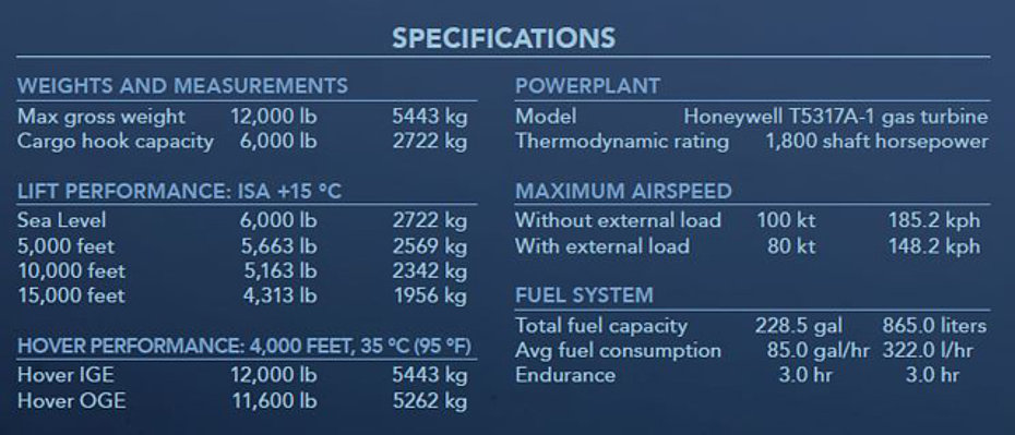
Performances
The helicopter's performance are summarised in the table below:

Weights and dimensions
The Kaman K-1200 K-MAX has an empty weight of 2,130 kg (4,700 lbs) while the maximum take-off weight is 2,722 kg (6,000 lbs) without external load, respectively 5,443 kg (12,000 lbs) with external load. The helicopter can carry a maximum slung load of 2,720 kg (6,000 lbs).
The main dimensions of the helicopter are shown in the drawing below:
")
")
The Kaman K-1200 K-MAX in Switzerland
The Swiss company Helog AG (Helicopter Logging) founded in Küssnacht (Canton Schwyz) in 1982, became the first European operator to purchase a Kaman K-1200 K-MAX in 1995. Specialized in logging and heavy transport with helicopters, it used large helicopters such as the AS 332C1 Super Puma.
Its first K-MAX with call sign HB-XHJ was presented as already said in 1995 during Helitech '95 and entered immediately into service piloted by the then chief pilot Heinz Leibundgut.
In April 1, 1997, together with a number of investors, including David Vogt (Rhein Helikopter), Leibundgut become the chief-pilot of the newly founded Rotex Helicopter AG in Balzers (Principality of Liechtenstein), an independent company founded to provide a professional and reliable service for customers with medium-weight loads.
This operator is currently the only one using the K-MAX in Switzerland. Since its foundation, its fleet has completed a total of more than 45,000 flight hours, transporting on average hundreds of tons per day!
")
The opinion of a pilot
Raffaello "Raffo" Milani, born in 1978, is the only pilot in Canton Ticino and among the few in Switzerland who has the type-rating on the Kaman K-1200 K-MAX. Thanks to him it has been possible to get acquainted with this original helicopter on which to date he has logged a total of over 2,700 hours of flight of the 7,500 he has under his belt. In 2014 he was hired as a helicopter pilot by Rotex Helikopter AG.
Our interlocutor explains that in order to obtain the type-ratying on the K-MAX it is first of all necessary to be in possession of an American helicopter pilot license. In his case, as he already holds an EASA license, obtaining those issued by the Federal Aviation Administration (FAA) wasn’t any particular problems.
The theoretical training course lasts about fifty hours and takes place over ten days at the Kaman Aerospace plant in Bloomfield and allows the pilot to acquire the necessary knowledges.
Since the K-MAX is a single-seater aircraft the pilots are trained on a Kaman HH-43B Husky owned by Kaman Aerospace (N43FK) which has similar flight characteristics to the K-MAX.
Raffaello Milani together with Elan Head, an aviation journalist and flight instructor (she was the first woman to qualify on the K-MAX), started the course in December 2014 and describes his first flight on the Husky as follow: "I must admit that immediately after the first start I was rather puzzled and I also asked myself: where did I end up? Buckled up in our seatbelts, me and instructor Bill Hart, Kaman Aerospace's chief pilot, were jolted by the swaying of the aircraft, a very strange feeling that I had never experienced before at the controls of other helicopters. - Don't worry, it's normal " said Bill to calm me down "you'll get used to it. I remember that after the first flying lesson I was exhausted and quite disappointed. However, as I continued my training I slowly learned to appreciate the qualities of this aircraft. Let's say that you have to enter into its philosophy, but let's be clear one thing: either you like the K-MAX or you hate it, because it is not a helicopter like all the others! Some pilots in fact after having flown this helicopter for a few months then decided to quit".
After about 6h30' with the flight instructor on the Husky the pilot is ready to sit at the controls of the K-MAX. After the first flights "to feel the control" the new pilots become familiar with carrying slung loads. They start with 907 kg (2,000 lbs), then (1,814 kg (4,000 lbs) and by ending 2,268 kg (5,000 lbs).
Under the instructor's supervision, the pilot completes an additional 6 hours or so of flight time and is generally ready to start with commercial operation.
After his return to Switzerland, Raffaello Milani took an examination with Thomas Bolzli, another K-MAX pilot and expert on behalf of the Federal Office of Civil Aviation (FOCA) who observed his maneuvers from the ground. Afterwards he performed the first 100 hours of flight under the supervision of another company’s pilot.
")
")
K-MAX at work
Along the valleys of the Swiss Alps the Kamans operated by Rotex Helikopter AG can be seen frequently. They are mainly used for logging operations. "Thanks to its lifting capacity and quietness, it is a very appreciated working tool for forestry jobs" explains Raffaello Milani. "The Rotex team usually includes 4-6 flight attendants, 3-4 of whom are scattered in the forest and are responsible for hooking the loads prepared by the forest teams, while the others are in charge of recovering the chockers, stacking the logs using the helitrac (a special vehicle equipped with hydraulic telescopic clamp), and refueling. It's a teamwork that requires the right men to be really efficient.
The necessary material is transported on a van while a large truck is used to refuel the aircraft. The K-MAX burns an average of 330 liters (87 USG) of kerosene per hour of flight. We fly with a reserve of about 1h-1h10'. During the day two pilots seat alternatively at the controls. On average, each pilot flies about 5 hours. On the most demanding days the K-MAX also performs 10-12 hours of flight time. The 25 or 50 hours technical inspections are often carried out in the field. The K-MAX is a real flying mule, and like the equine it is very rustic.
The transport cable generally used for logging operations has a length of 55 meters (180 ft). This allows us to operate while maintaining the necessary safety distance from the top of the trees.
Thanks to the characteristic V-shape of the fuselage, the pilot has an excellent downward view and observes directly the flight assistants while they hook the logs. The round mirror that can sometimes be seen in front of the cabin actually serves only to control the opening of the barycentric hook. As I lift the load I monitor the three instruments that indicate respectively: load weight, torque and EGT (Exhaust Gas Temperature).
The piloting technique varies depending on the terrain morphology. In narrow valleys where there is a considerable difference of altitude between the loading and unloading point, but between the two points there is a short distance, after lifting the load above the top of the trees, I let descend the helicopter at very low speed (10-15 knots) trying to not let raise the rotors rpm speed above the allowed limit.
In this phase of the flight, care must be taken not to enter vortex (the vortex ring state is a potentially dangerous aerodynamic condition that may arise in helicopter flight, when a vortex ring system engulfs the rotor causing severe loss of lift. Vortex ring state is sometimes referred to as settling with power. If this occurs the helicopter begins to be shaken with a frequency that assumes a sort of rhythmic vibration of the cabin. Observing the variometer the pilot can read unusual rates of descent, which can increase when the pilot instinctively activates the collective step, worsening the situation. The loss of altitude is important, so it is necessary to act correctly on the controls).
The K-MAX gives almost no warning signs. You realize you are in a vortex situation when you read on the variometer descent values in the order of 3,000-3,500 feet per minute! In this case the helicopter stops more easily than other models: it is sufficient to pull the collective adding at the same time a bit of cyclic.
In certain phases of the flight the pilot when operating the pedals has to expect different reactions, especially when the helicopter is not carrying loads the response is slow. For this reason in close proximity to the ground you have to be very careful and manoeuvre with great caution".
")
The K-MAX is not afraid of the wind, even on foehn days (föhn or phoen is a type of dry, warm, down-slope sometimes impetuous wind that occurs in the downwind side of a mountain range, in different baric configurations, on both sides of the Alpine chain). "The helicopter places itself in the wind axis like a flag thanks to the large vertical stabilizer. Sometimes it is necessary to follow the reactions of the helicopter and not try to waste time to correct them, the K-MAX is like this!“.
The lifting capacity of the helicopter is really remarkable. The structural limit of the barycentric hook is 6,000 pounds (2'722 kg), a weight that the K-MAX does not have any difficulty to lift in the pre-alpine areas (400 to 2,500 meters – 1,310 to 8,200 ft) in standard conditions.
Pilots observed that when carring dense, heavy 2,000-2,500 kg (4,400 – 5,510 lbs) external loads on a long line without a damper, it is possibe to encounted vertical oscillations of the aircraft, usually induced when a descent is commenced at higher airspeed (65-80 kts). These oscillations can magnify to dangerous proportions if not corrected quickly. Increasing collective with simultaneous reduction in airspeed will reduce/eliminate the oscillations.
")
For high mountain operations mechanics can manually correct the angle of attack of the servo-flaps by using the turnbuckle.
Among the most frequent uses in addition to logging are aerial assembly (of cranes, cable cars, chairlifts, pylons, power lines), refueling of construction sites and transport of vehicles and work vehicles in remote areas. Occasionally it is also used for fire-fighting operations.
"In my opinion - affirms Raffaello Milani - to know K-MAX really well it is necessary an experience of about a thousand hours of flight. In this period the pilot refines his piloting technique. Despite the initial skepticism nowadays I can affirm that I am a true fan of this helicopter that I always fly with great pleasure. The ergonomics of the cockpit is very good as well as the layout of the flight instruments.
Did you know that…
After an agreement signed in 2008 Kaman and Lockheed Martin performed several demonstrations on behalf of the U.S. military armed forces with an unmanned version of the K-MAX.
Two aircraft were later successfully used to deliver thousands of supplies and equipment to soldiers deployed in Afghanistan between 2011 and 2014. Under the supervision of the operator day and night more than 2,000 tons of material were airlifted through territories considered too risky for a pilot.
Here is an interesting link about this employ:
https://www.lockheedmartin.com/content/dam/lockheed-martin/rms/documents/K-MAX/K-MAX-brochure.pdf
On November 6, 2014 at the Griffiss International Airport in Rome (New York) an unmanned K-MAX demonstrated its firefighting capability.
Using geo-referenced data transferred from an Indago quadrotor drone equipped with an infrared to the K-MAX through a ground control operator, the helicopter autonomously performed multiple firefigthing missions including fire suppression.
Here is an interesting article appeared on the press: https://www.auvsi.org/K-MAX-demonstrates-firefighting-capability
Videos
Watch these videos with the K-MAX at work.
The unmanned K-MAX helicopter in Afghanistan: https://www.youtube.com/watch?v=jIFazapnnZU
Aerial assembly of a power line: https://www.youtube.com/watch?v=TwwiZ-LyNVQ
Logging operation: https://www.youtube.com/watch?v=KCmt-WDkScc
Delicate log removal close to a power line: https://www.youtube.com/watch?v=hZ7Ewox1lV0
Interesting links
Visit the website of the Swiss operator Rotex Helicopter AG: https://www.rotex-helicopter.ch/it/
For more information on the turboshaft visit: www.t53.com
Visit the official site of Kaman: www.kaman.com
Acknowledgements
Special thanks go to my friend Raffaello "Raffo" Milani who helped me to complete this article with first-hand information.
HAB 12/2020