

")
")
 discusses with flight engineer Bernard Certain (archive B. Certain)")
")
, along with Georges Petit and Fernand Carayon discusses the outcome of the first flight along with flight engineer Bernard Certain (archive B. Certain)")
The helicopters of the AS 350 Ecureuil series (squirrel in French) were introduced in Switzerland 40 years ago: the first with call-sign HB-XGW was in fact put into operation by Linth Helikopter AG based in Mollis (Canton of Glarus) in April 1979.
Taking a cue from an old report dated May 1977 prepared by the famous French engineer René Mouille (1924-2019) here is an article that summarizes the history of this lucky helicopter.
Origins and development
The AS 350 project was born under the direction of Fernand Carayon, then industrial director of the Division hélicoptères of the Societé Nationale Industrielle Aerospatiale based in Marignane/France.
During 1971 the company executives came to the conclusion that the time was ripe to develop the successor to the Alouette 2.
Although the SA 341 Gazelle was also a five-seat helicopter, this helicopter with brilliant performances had been developed for military uses and only later adapted to the civilian needs. However, its operational costs made it unattractive for operators. The main objective aimed at for the development of the AS 350 was the reduction in production and operating costs.
The French engineers who had a considerable know-how then began to study what were the opportunities offered by the progress made in the technical and technological field. To achieve their objectives they benefitted from progress made possible by their major research effort, under way since 1966, to simplify the principal systems of the helicopter, particularly the rotor. Experience gained in the general aviation field was used to lower the cost of structure elements.
In 1972 after the project conceptual phase completition, the helicopter was further developed in an autonomous production unit, to benefit from the advantages a small team, grouped together but supported by the technical depth of the Engineering and Production departments.
In spite of the numerous innovations and the additional work for cost analysis and design finalizing, the development was completed in a relatively short time while keeping withing budget limits.
Right from the design stage, the search for the most economical solutions, carried out with the help of production engineers, integrated into the design team, has called for the creation of new techniques and the application of new technology.
Over a period of two years brand new solutions had been thought out, which led in early 1973 to a preliminary project whose cost in quantity production could be approximately assessed. Among these there were:
- the innovative Starflex rotor head
- mechanically produced glass/resin composite blades
- the two-bladed tail rotor molded on a single torsion strip also made of glass/resin composite material
- the rotor flexible suspension based on laminated elastomer
- a thermo-formed plastic canopy
The results of this work being very encouraging the decision to lauch the “development” operation including detail designs, production and flight testing of two prototypes was made with an ambitius objective of production price, resulting from the outlooks given by the preliminary project. This development work began in April 1973 under the authority of a responsible person coming from the engineering department.
As you will discover the history of the AS 350 is exemplary in many aspects. Indeed it was Aérospatiale first helicopter whose development had been undertaken with cost as the priority target and in which the production personnel took part, from the early design stage, in an endeavor to minimize production costs.
Previous models were designed for military use with specifications and performance that had to be achieved at any cost. The AS 350 instead had been designed for the civil market, for this reason the economy was of priority importance. The organisation once set up, was also given the task of cutting down development costs as the founds allocated were considerably reduced in comparison with usual military budgets. Finally with the company-sponsored approach taken it was possible to select the best “cost-efficient” compromise without having to strictly adhere to “a priori” established – but sometimes unnecessary – specifications. The overall architecture was tought out with a view to reducing the number of assemblies to a minimum, simplification of shapes, deletion of difficult machining operations and unnecessary close tolerance that is had been possible to design simple, reliable, and low cost components.
In comparison with the Alouette 2 and Gazelle the AS 350 required nearly 3.5 times fewer production hours for 3.5 times fewer number parts.
Analysts were given the task of determining production layouts and times corresponding to design, even before the detail drawings had been made, so that no assembly had been produced without its production cost being known beforeand. Therefore some components had to be re-designed several times prior to approval of their cost. High grade materials were utilized only in the case they were strictly necessary and selection was often guided by the production requirements.
Aérospatiale adopted car and lorry parts where appropriate. The main gear box oil cooler was almost the same of the Citrôen GS and cost one-tenth as much as its aviation equivalent. It was designed to a toughter specification and for a longer life. The oil-cooler fan motor driven, also an automotive part, cost one-hundredth as much as its aircraft equivalent. Several instruments came from cars. The windshield wipers were the same mounted on some Citrôen models. Among the other components mounted on cars or trucks of French production there were for example, different instruments, handles with door locks and a hydraulic pump which cost one third of the usual price. For safety reasons, the manufacturer was obliged to demonstrate the feasibility of this approach to French civil aviation officials.
With the exception of the main gearbox whose reduction in cost led to a weight increase of 12%, the economical solutions contemplated for the AS 350 proved to be lighter in weight than the corresponding solutions on the Alouette 2 and 3 helicopters. The exercise of reducing costs was remarkable and also certainly stressful, but the result as we know was a real success.
As Mouille reported, technical progress and the development of new materials and technologies made it possible to achieve goals that were unimaginable only a few years earlier.
Another aspect that should not be forgotten is the fact that the AS 350 was born from a team of technicians with specific skills in various fields capable of working together with the right spirit, what was not always possible especially in large companies divided into departments with employees who worked in “watertight compartments”.
It is precisely to the aforementioned Fernand Carayon (who occupied the position of director for 17 years starting from April 1967) that the merit of having reorganized the helicopter division of the Aérospatiale rehabilitating autonomous ateliers and establishing flexible schedules and training plans is to be credited. This man played a major role in the AS 350 program destined, as we know, to become one of the most successful French helicopters.
Time and dedication expressed at the highest levels and a correct vision gave birth to the new helicopter. The prototype initially registered F-WTNB (AS 350-001 - and then F-WVKH after a series of modifications) powered by an Lycoming LTS101-600A completed its first test flight at Marignane/F on June 27, 1974 in the hands of pilot Daniel Bauchart and flight engineer Bernard Certain who participated in the development of the AS 350 program from the earliest stages.
")
")
")
Modifications on the prototypes
The first flights revealed among other problems excessive efforts on the tail rotor hub. In July 1974 the changes introduced reduced the effort, but only with the adoption of a hydraulic servo to assist the tail rotor control the problem was definitively overcome.
The AS 350 initially also showed instability problems along the pitch and yaw axes. Several modifications were tested such as a twin vertical fin or a T-shaped fin similar to the one mounted on the SA 341 Gazelle.
")
")
The cabin had also to be modified and stretched. Daniel Bauchard with his 190 cm height was far from being comfortable at the controls of the helicopter. The same Bernard Certain was forced to shift his seat back 5 cm beyond the rear limit initially envisaged to sit confortably. This explains why the first prototypes had a single door on each side. To facilitare the access a second smaller door on both sides of the cabin was added. Another important problem with which the French technicians were faced were the strong vibrations coming from the main rotor. In some old photos with the first prototypes it is possible to observe the Starflex rotor with a bi-filar vibration damper. In fact Aérospatiale resorted to this type of solution to dampen vibrations at high speeds. Although heavy and difficult to produce, the system worked, but then the French engineers were forced to revise their plans because Sikorsky claimed a patent on this invention.
")
For this reason René Mouille developed a new rotor head spring type anti-vibrator, which was more efficient, simpler and lighter. It also had the advantage to be set on the bench without turning the rotor. All the models of the AS 350 now adopt this system.
To further improve the comfort of the occupants (in particular at pilot’s seat), cabin resonators attached to the end of a flexible steel blade are located under the pilot and co-pilot’s seat.
Efforts on the flying controls, especially at high speeds, prompted engineers to install accumulators. In this way, in the event of a fault in the hydraulic system, the pilot would have a reserve to reduce the speed.
The second prototype with serial number F-WVKI powered by a Turboméca Arriel 1B turbine made its maiden flight on February 14, 1975. Its general look was a bit different from the model then manufactured in series.
")
It will be called Ecureuil/Astar
As Bernard Certain affirms at the beginning, when the project was launched, people usually referred to the AS 350 as the “Business Alouette” or the “low-cost helicopter”. For marketing reasons it was therefore necessary to find a suitable name and so continuing with the tradition François Legrand director of the Division hélicoptères chose the name Ecureuil (squirrel), perhaps inspired by the agility of the helicopter.
On March 9, 1976 Aérospatiale formally launched the new AS 350 and during a press conference by vote of the journalists chose the name “Ecureuil” (Squirrel).
In France the new appellation was immediately welcomed with enthusiasm, but in the United States, someone thought, the correct pronunciation would have been quite difficult. Furthermore for some the presence of squirrels is sometimes seen as an annoying problem.
It so happens that when the prototype of the AS 350 was unveiled the movie "A star is born" (1976) directed by Frank Pierson and starring Barbra Streisand and Kris Kristofferson appeared. The film (a remake produced and directed by Bradley Cooper strarring the famous singer Lady Gaga appeared again last year) and soundtrack (which contained the omonymous song played by Barbra Streisand) obtained a great commercial success and someone at the Aérospatiale Helicopter Corporation, the French manufacturer’s US subsidiary in Texas, inspired by the American musical romantic drama film decided to designate the AS 350 with the name "Astar".
In the United States the AS 350 Astar was officially presented at the 29th edition of the Helicopter American Association (HAA) which was held in Anaheim between February 6 -9, 1977.
The helicopter initially needed a complete overhaul every 4'800 hours or after 9 years.
The AS 350C obtained the French civil certification issued by the French authorities (DGAC) on September 2, 1977, while type certificate for the AS350B was released on October 27, 1977.
The prototypes were followed by a pre-series of 8 aircraft the first of which flew towards the end of 1977 with call sign F-WZAG.
A career in jeopardy
Unfortunately, on April 6, 1978 there was a serious accident involving s/n 1006 (F-WZFM).
During a demonstration test flight pilot Henri de Riols de Fonclare informed the control tower of Marignane that he had a problem and that he intended execute an emergency landing. Witnesses confirmed that flames and smoke were coming out from the engine compartment.
Forced to perform an autototation, the pilot flew over a power line but in the next maneuver to avoid another pylon he had not previously seen he lost the rotor rpm. The helicopter hit a large tree and the fuselage broke into two stumps and fell back onto the road near the small La Fare Les Oliviers airport about 5 km west of Marignane.
On the impact, the 41-year-old pilot who had logged more than 4,000 flying hours under his belt, Helmut Langfelder president of Messerschmitt-Bolkow-Blöhm (MBB) and General André Thoulouze delegate of Aérospatiale in London lost their lives.
Jean-Charles Poggi personal assistent to Aérospatiale chairman General Jacques Mitterrand, and Gustav Bittner personal assistent to Langfelder were seriously injured.
A plaque on the site of the accident reminds the victims.
After the tragic accident, the scheduled deliveries of the AS 350s powered by the Arriel 1B turboshafts were temporarily suspended until the causes of the crash were clarified.
Commercial success
Despite the incident, the sales of the AS 350C started with a bang, even if then this version was plagued by problems caused by the Avco-Lycoming LTS101-600A. Some pilots and technicians sarcastically nicknamed this version the “falling star ".
The situation was so serious that in an article published on the magazine Flight in March 1980 Aérospatiale Helicopter Corporation announced that it was considering an Allison 250-powered version of the AStar. The idea was then abandoned because the certification would have taken about two years with consequent delivery delays, and field support of three different engines on the AS 350 would have been too expansive.
The first AS 350C was sold to Helicopter Associates of Phoenix/Arizona. Among the first important customers there was Petroleum Helicopter Inc. which announced in February 1977 that it had purchased 20 AS 350s.
In August 1977 the aircraft sold were already around fifty, while the same number were already on the list of orders, that is to say the entire production capacity scheduled for 1978. By mid-November 1978 Aérospatiale had received 177 orders.
The sales success was such that in March 1979 the French manufacturer announced that the production capacity would be increased from 10 to 20 aircraft a month by the end of 1980.
At that time (May 1979) the AS 350D (which replaced the AS 350C and which was was powered by a more powerful Avco-Lycoming LTS 101-600A.2) was sold at a price of 335,000 USD, while the price for a Bell 206B Jet Ranger III was about 225,000 USD and 385,000 USD respectively for the Bell 206L-1 Long Ranger.
Clarified the causes of the accident occurred on April 6 (the mechanical failure was caused by an inadequate lubrication of a bearing in the Arriel 1B engine), and after the introduction of minor changes to the oil system, the first AS 350B manufactured in series was sold in July 1978.
It is interesting to mention that a team of engineers reduced production costs not only thanks to a rational design, but also thanks to a careful analysis of the assembly line which was conceived following the example offered by the automotive industry with a very short assembly cycle in which there were pre-assembly stations very close to the main assembly line. In an effort to improve the production process, the employees were not sacrificed.
Aérospatiale's management practiced a so-called "job enrichment" policy to have the helicopter assembled from start to finish by the same team of workers. These workers even performed power check at the end of the assembly line. Thanks to the “fini-parti” principle workers were stimulated to work with more interest and efficiency.
Ten years after its introduction on the market, the AS 350s fleet had completed 2,400,000 flight hours with 520 operators in 55 countries.
As correctly forecasted by the executives of the helicopter division of Aérospatiale, which at that time occupied a total of about 7,800 employees, the civil operators greatly appreciated the qualities of this aircraft, which in the various civil and military versions has been manufactured in over 5,000 units.
")
")
A part of them was manufactured under license in Brazil by Helibras - Helicópteros do Brasil S.A with the designation Esquilo.
Nowadays in its most recent versions it is one of the most successful single-engine helicopters.
Forty years after his appearance in Switzerland, it has almost completely replaced the venerable SA 315B Lama.
The innovation of the Starflex
The AS 350 was equipped with the "Starflex", an innovative main rotor built largely with materials such as glass cloth and a special epoxy resin which gave it significant improvements in terms of mechanical complexity, weight, reliability, cost, flight performance and maintenance.
")
")
The Starflex was tested for the first time on February 14, 1974 on the SA 341-001 Gazelle. Its design had then been improved trough successive stages, the aim being to reduce weight and cost. Steel sleeves (grips) for example were replaced by fiberglass-wound sleeves wich were themselves simplified at a later stage while pitch change horns developed from machined forgings to pressed steel plates.
Description of the Starflex
The Starflex rotor head consists of a center STAR-shaped body made of glass cloth and epoxy resin moulded and cured in an oven. The star, which is bolted to the rotor shaft, has three arms flexible flapwise (FLEX) and it is the rotor basic component.
")
The Starflex rotor head principle is to link the blades to the star arm by means of a rigid sleeve ensuring, without bearings, the flapping, drag, pitch change functions.
The sleeve made of would glass and resin yarn must also transmit the blade centrifugal loads to the non-flexible center area of the star. For this purpose flexible links have been provided between the sleeve (3) and the star arm (1). The lamitated spherical bearing (2), sandwich made of steel cups and thin elastomeric sheets, is flexible in torsion, flapping and drag, but it is rigid in compression.
The two elastomeric flanges (4) distorting under shear load provide the elasticity and dampening required in drag. The latter replaces conventional lead-lag dampers. The Starflex is a so-called “hingeless” rotor.
The self-lubricating spherical bearing (5) centers the sleeve at the end of the star arm.

The progress made with the introduction of this new generation of rotors is remarkable for different reasons. The mechanical complexity for example has been considerably reduced.
The following table shows some interesting comparisons between the rotor of the SA 318 Alouette 2 and that of the AS 350 Ecureuil:
")
Hereafter are listed some advantages of the Starflex with respect to a conventional hinged rotor:
- practically no maintenance (no hinge, no lubrication required)
- “fail safe” characteristics owing to the use of composite materials (any possible damage progress very slowly and therfore should be visible during inspections)
- modular design: all parts are bolted together. It is easy to replace the critical element (sperical bearing, elastomeric flanges)
- low weight
The resistance of the materials used is truly remarkable which means high resistance to fatigue, great resistance to impacts, little sensitivity to corrosion.
The star of the Starflex was originally designed to have an operating life of 2'200 hours, sleeves 5,000 hours and elastomeric laminated bearings 6,400 hours.
Compared to a semi-rigid rotor like that of the SA 341 Gazelle, the Starflex is technically simpler, offering a weight saving of 40% (compared to the Alouette 3 the weight saving is almost 50%, that is 55 kg instead of 105 kg), a 50% price reduction. Production cost of the head was about 40% of the cost of a conventional articulated rotor head.
")
")
Below the characteristic circular protection similar to a frisbee (1) placed on the top of the rotor there is a spring (2) type anti-vibrator. An inverted pendulum (3) also known as vibrating weight is located on rotor head centre-line. It is held by three springs allowing it to flap (to vibrate) in the horizontal plane and in all directions. The weight spring system excited by the periodic alternated loads applied to the rotor head responds to the excitation frequency in such a way that it opposes exctitation loads and dampens its vibration.
Technical description
The AS 350B Ecureuil is a light single turbine helicopter of standard configuration which can accomodate up to 6 passengers. The fuselage of the helicopter is divided into four main sections: the cabin, the central section, the rear section and the tail boom. Altogether the structure includes about 300 parts against the 1000 of an Alouette 2.
So-called reinforced plastics were used for the construction of the cabin and the fairings of the central structure. The canopy is made of polycarbonates. Just a few words about these materials, a novelty in the early 1970s. They are synthetic resins divided in two main classes:
- termoplastics which soften when heated and harden when cooled. For instance: polyamides (Nylon, Rilsan), polycarbonates
- thermosetting resins which under compined action of heat and a hardener cure when heated (in an irreversible manner) giving a new material. For instance: epoxy resins, and silicone;
Laminates and laminated honeycombs are reinforced plastics which have very good mechanical strenght properties. Laminated materials are produced from thermosetting resins and reinforcing materials (glass, carbonate, graphite, bore fibers). The reinforcing fibers are laid out in mat or woven from the impregnated with the basic resin. Several layers of mats or clotch are stacked and then, placed in a mold and cured. Direction of the reinforcing fibers depends on the load to be transmitted. The laminated honeycombs includes a honeycomb core (metal, glass cloth, or Nomex) each face of which receives one or many pre-impregnated layers. The whole assembly is oven cured. The external shape is achieved by moulded cowlings made of fiberglass-resin laminates.
The cabin
The cabin has a volume of 2.85 cubic metres (105.943 cu. ft.) and its frame component are: the cabin roof, the nose and the vertical members. The cabin is made of thermoformed polycarbonate panels assembled by an ultrasonic bond-welding process reinforced with glass fibers. Its frame is bolted to the cabin floor and the body structure bulkhead which also acts as a backrest for passengers seated behind. The bottom structure supporting the cabin is of the cantiveler type and forms an extension of the body structure. It is bolted to the floor and rests on two side members that extend frontally from the central section and to the bulkhead slanted backwards of 15° which also acts as a backrest for passengers sitting behind.
")
The cabin offers space for 4-5 passengers depending on the configuration (comfort or standard). The pilot sits on the right and the co-pilot or passenger on the left, while the other occupants are seated behind side by side.
In the standard configuration they sit on two benches (2 x 2), each of which can be individually folded. When necessary the helicopter can be quickly converted for the transportation of goods. An optional kit allows the transportation of six passengers (two seated in front beside the pilot, four behind).
The front seats made of fiberglass can be shifted fore and aft. However, unlike the latest versions of the AS 350 (B3, B3+, B3e), they are not of the anti-crash type.
The access to the cabin is possible through two main doors one on either side, giving access to front seats, and two small doors giving full access to the rear section.
For some missions (hoisting – casualty evacuation) requiring a wide access to the cabin the helicopter is equipped with sliding door on rails which may be opened in flight and maintained in open position.
The cabin roof made of polycarbonate consists of half shells inside which air (and air conditioning when installed) for cabin ventilation is ducted. The large windshield panel offers a good visual in all directions. In the nose there is a landing light.
The flight instruments are grouped on the panel while circuit breakers, radio selectors and caution/warning light are on a center pedestal.
The center and rear section
The center-section is the airframe’s strongest stucture since it directly supports flight (lift and weight) and landing loads. The main structure is designed as a rigid hexaedron.
It supports the main transmission components, landing gear, cabin floor, rear structure and encloses the fuel tank.
The result is a sturdy frame that includes the rear bulkhead of the cabin and the front bulkhead of the luggage compartment.
")
The upper part of this frame accomodates the transmission deck and the main rotor gearbox, rotor shaft, and rotor head mount assembly.
The 532-litres (140.55 USG) fuel tank is fitted in the center structure and strapped on two trasverse cradles. The use of the roto-moulding process reduced its cost by 90%.
Except for the two frames which naturally match the profile of the corresponding fuselage section, all other components are independent of the external shape and have simple and straight profiles with 90° stiffening flanges, which greatly simplify the manufacture. The external shape is achieved by moulded cowlings made of fiberglass-resin laminates. The bottom structure, supporting the cabin, is of cantiveler type and forms an extension of the body structure. Two beams reinforced by cross members are bolted on main structure lateral beams and support the landing gear at it forward end.
The central structure, as already mentioned, serves as a support for the landing gear, which protects the structure on landing and dampens the vibrations on the ground when the rotor is turning. The landing gear assembly comprises one forward cross tube and one rear cross tube (steel), two skids (aluminum) and two hydraulic shock absorbers.
A flexible steel strip bent clownwards extending at the rear part of the skids increases the landing gear flexibility and positions the natural frequency of the assembly in such a way that ground resonance danger is reduced to a minimum. In addition the shock absorbers placed between the landing gear forward flexible leg and the structure, are intended to absorb the vibration energy and this eliminate almost any oscillation divergency.
Flexibility of cross tubes, skids and their steel strips permit to reduce vertical deceleration when the helicopter touches down. On the other hand impact energy is absorbed by the shock absorbers and by friction of skids on the ground. On this regard special wear pads made with steel protect the skids from abrasion.
Helicopter ground handling wheels are attached to the skids, allowing for the user to easily balance the aircraft during maneuvering without the tail hitting the ground.
")
The rear structure connects the center frame to the tail boom and consists of three frames connected by beams. The rear and forward frames support the engine. The tail boom is bolted to junction rear frame and can be easily removed. The rear structure also contains the main luggage compartment. The upper part of this frame is the engine deck and is made by stainless steel plate.
On both sides there is a foot rest used by mechanics for technical ispections. On the left side there is the access to the baggage compartment which has a volume of 565 litres (19.95 cu. ft.) and where, respecting the centering limits, it is possible to load up to 80 kg (176 lbs). Its door hinged at the bottom is made by reinforced plastics.
The upper part of the central structure is covered with partly constructed cowlings with laminated honeycomb structure (laminated honeycomb) and aluminum alloy developed for the Concorde supersonic aircraft, while the lower mounted cowlings are constructed with materials reinforced plastics (laminates - reinforced plastics). Front lower fairing laminated.
The oil cooler air intake is made of laminated polyamide, and the MGB upper cowlings with laminated panels. The engine cowling is made with Nomex-aluminum protected honeycomb and it is hinged on firewall.
")
Main gear box
The main gear box transmits the engine torque to the main rotor after reducing the rotational speed from 6,000 rpm to 390 rpm and changing its direction by approximately 90°. It also transfers the reaction torque from the main rotor, through its casing, to the aircraft structure. The main gear box has a pressure lubrication system monitored by “low pressure” and “high temperature” warning lights.
Trasmission oil level and hydraulic reservoirs for the aircraft three control servos can be viewed either by opening a large access door on the left side of the aircraft, or by peering though a small window in the door.
The main gear box which supports the rotor mast assembly in which the rotor shaft is inserted receives from this shaft vertical and horizontal periodical alternated loads. Any rigid attachment of the main gear box onto the transmission deck would transfer there vibrations to the structure. The solution consists in using a flexible suspension between the main gear box and the structure which is said filters the major parts of the vibrations. The main gear box and main rotor assembly is attached to the structure at two levels. At rotor mast by four rigid bars which transfer the lift from the rotor to the structure. At main gear box by a flexible suspension fitted between the bottom of main rotor gear box and the structure which picks up longitudinal and lateral loads and torsional moments. The main gear box is suspended as a pendulum and oscillates about a determined point.
This solution is, in its principle, identical with that of Puma or Gazelle, with attachment bars converging at a point on the rotor shaft and a flexible link between main gear box bottom and the structure. However the design of this flexible mount is different.
The main gear box lower casing, molded into a spiral rests on the structure through two groups of laminated elastomeric pads which transfer the torque with almost no deflexion while allowing the horizontal displacement of the main gear box bottom.
An intermediate “dog bone” shaped component is required to balance the loads applied to the elastomeric pads. The engine as coupled to the main gear box partecipates in the system dynamics. This very simple, light and cheap system is highly efficient.
The main gear box of modular design is composed by three modules: an epiclyclic reduction gear, a bevel gear housed in two casing (a main casing supporting the power input and a lower casing providing main gear box attachment to flexible suspension assembly) and a hydraulic pump that power the hydraulic system on the lower casing. The rotor brake is fitted on the main gear box power input.
The main gear box has been designed with the aim of maximum simplification, high reliability and minimum production and operating cost. The number of components has been reduced to a minimum. This is the reason why a reduction gear with only two stages (a couple of bevel gear and epicyclic stage) has been selected instead of three stages as in the Alouette or Gazelle main gear box. This design is about 12% heavier but much simpler.
During the initial tests the MGB ran without oil for almost two hours before being shut down because smoke was coming out.
The tail rotor power take-off has been deleted, as mentioned above, due to the engine layout and, except for the oil pump which is driven directly by the bevel ring gear support shaft, there is no accessory drive. The number of gears and bearing has more than halved and the production cost was reduced in about the same proportion while the operating costs was divided by three because of the large dimensioning of gears and bearings. The estimated production cost or the AS 350’s main gear box was 59% of that of the main gear box of the Alouette 2, and operating cost of only 21% of the Alouette 2. The construction of the main gear box has remained essentially the same and is mounted on the entire AS 350 series to the present day.
")
Tail boom
The tail boom consists of circular frames covered by an outer skin. Assembly rigidity is ensured by sheet metal stiffeners. The tail boom supports:
- the tail rotor gear box mounted on a reinforced frame
- the horizontal stabilizer attached between two reinforced frames
- the tail rotor drive shaft which comprises two sections (one short drive at MGB output - reduction gear module -, one long drive shaft both are protected by hinged fairing)
- the vertical fin
The lower vertical fin is protected by a tail rotor guard in the event of an excessive nose up landing.
The stabilizer and fins are stabilizing surfaces having an airfoil section, which when submitted to relative wind have a tendency to prevent change in aircraft attitude, bring the aircraft back to its initial attitude in case of variation.
The horizonzal stabilizer has a dissymetrical airfoil section and it is set at -2° angle from the horizontal datum and produces with the relative wind an aerodynamic force tending to level the aircraft. The upper fin has also a NACA dissymetrical airfoil section and produces in cruising flight an aerodynamic force opposing the reaction torque of the main rotor, thus acting in the same direction as the tail rotor, therefore tail rotor blade pitch may be reduced and hence less power is required. The lower fin has a NACA symmetrical airfoil section. At the rear end there is a handling bar.
")
The tail rotor
In an interview dated May 1977 René Mouille stated “One may ask why the AS 350 subsequently to Gazelle and Dauphin is not fitted with a shrouded tail rotor (Fenestron). It is only because of its lower price that a simplified conventional tail rotor has been selected. However this does not preclude that one day, a Fenestron may be installed on the AS 350 as recent studies have shown that it could be manufactured at a price very close to that of a conventional tail rotor and at slightly lower weight”.
Indeed as we know Aérospatiale tested a model known as the AS 350Z F-WYMZ fitted with a Fenestron. This model completed the first test flight on February 6, 1987 piloted by Pierre Loranchet.
However the series was produced with the conventional tail rotor mounted on the right side that runs at 2'043 rpm, while the Fenestron was mounted on other helicopters such as the EC-120B and the EC-130B4.
The two-blades tail rotor was of a new technology too. The blades have a chord of 185 mm and a NACA 00.12 profile. They are made of fiberglass epoxy resin composite material, and moulded directly on the same glass roving beam. The assembly is articulated in “see-saw” manner about a cross shaft swivelling on a self lubricated plastic bearing. At its center part, the blade skin ends in a cuff resisting on a laminated elastomer bearing which allows for pitch variation by torsion of the inner beam, left free in this area. The reduction in weight is about 40% compared to the Alouette 2 two-blade tail rotor and its price was 75% lower. Moreover no maintenance nor lubrication is required. The tail rotor has a diameter of 186 cm and weighs 4.6 kg. Operation of this rotor has proved very satisfatory.
")
 1 stainless steel leading edge strip - 2 blade skin (2 glass cloth plies) - 3 glass roving winding (4 plies) wrapped around spar and core - 4 glass roving spar - 5 / 6 moltoprene foam core - 7 glass roving fil")
1 stainless steel leading edge strip - 2 blade skin (2 glass cloth plies) - 3 glass roving winding (4 plies) wrapped around spar and core - 4 glass roving spar - 5 / 6 moltoprene foam core - 7 glass roving filler - 8 leading edge protection (polyuretane sheet integreted in airfoil - lower surface and blade tip)
Main blades construction
The main rotor blades are entirely of fiberglass and epoxy resin composite. From their geometrical features, they are quite similar to the SA 341/342 Gazelle blades with the same chord. However the definitely differ by their cost which is a function of the manufacturing process. While Gazelle blades are manufactured almost entirely by hand, with laying out the components one by one in the mould, the blades of the AS 350 were manufactured by a more mechanized process. The spar for instance is made by machine winding in rovings for longitudinal elements and by 45 degrees cross windings for a good torsional stiffness. This spar is then fitted with a stainless steel leading edge and a glass cloth trailing edge, and filled with foam.
Resins used in blades manufacture are sensitive to the sun’s ultra-violet rays and therefore are protected by polyurethane paints.
Blades are attached to the sleeves through two pins held by a locking pin. On each pin, a safety pin acts in the same manner (double safety). A bonding braid ensures the continuity between the metal parts on the blade and rotor head. Main rotor blades can be folded using a special kit.
Because of the manufacturing process, the AS 350 blades are produced at a cost almost one-third that of the composite Gazelle blades and also appreciably lower that the cost of the Alouette 2 and 3 metal blades which are of a very simple design. Moreover they have the reliability, fail safe ruggedness features of the Gazelle blades.
")
Flying controls
Without power assistance the AS 350 has a powerful stick-to-the-right tendency which is too heavy to accept suddenly at high speed. The loss of the hydraulic system imparts a strong rolling moment to which the pilot must react quickly to stop the aircraft from entering an unusual and dangerous attitude. Should the pressure system fails, a horn and a light warns the pilot who must quickly slow down from any speed or attitude to level flight at 80 knots.
One solution to this problem would have been to incorporate a redundant servo system, but this was rejected because of the added cost and complexity in entailed.
In the early days the force was counteracted by a strong spring in the control runs. This crude palliative was then superseded by a new system.
")
")
")
Because it is possible for the pilot to counteract the adverse roll force when the aircraft is flying less than 80 knots, the alternative selected was to install a hydraulic accumulator that compensate for a few tens of seconds for the right roll forces on the stick in case of hydraulic failure. This should be enough time for the pilot to recognize the situation and slow the aircraft to 80 knots or less at which speed as said the aircraft is controllable. When the safe speed is reached the stick pressure to the right remains but the aircraft can be adequately controlled and the accumulators are discharged, the helicopter reverts to manual control. The pilot opens the solenoid valves by depressing the “hyd cut off” push button on the collective lever to eliminate any residual pressure or back pressure on the servo control pistons, and thus to reduce the mechanical loads required to move the control linkage. The right-wing-low tendency can then held conveniently by pressing the right knee against the stick. Even if somewhat unconfortably the pilot can chose a suitable landing place.
The reservoirs are automatically charged whenever the engine is started by a gear pump driven by a belt on the engine main gear box drive shaft (outflow 6 litres/min). The mean capacity of the hydraulic reservoir is 2.10 litres. A regulating valve maintains a constant system pressure at 40 bar.
Before take-off the system can be checked by manually switching off pump pressure and gently stirring the cyclic stick to exhaust the reservoirs and produce manual reversion. This take about ten seconds on the ground.
The AS 350 helicopter may be equipped with various type of servo controls (SAMM, DUNLOP, etc.) but the basic principles remain the same in all cases.
The three main rotor servocontrols are attached through rod end fittings on the main rotor shaft casing (anchoring point) and the stationary star.
The tail rotor servocontrol is anchored to the structure by means of an identical rod end fitting. The tail rotor pitch control rod fits onto the output mounting arm.
According to pilots the controls response is more rapid in the Ecureuil than in the Gazelle or Alouette.
Turboshaft Arriel 1B
The choice of the engine was also dictated by the need for simplicity and economy. For this reason a free turbine was selected: by doing this it was possible to eliminate the clutch unit with a weight saving of about 30 kg. Furthermore, since the power take-off of the engine was on the same axis, it was possible to eliminate a pair of bevel gears in the main transmission as well as an intermediate gearbox and a section of the transmission shaft of the tail rotor.
The drawing below shows schematically the differences and the simplifications between the main gearbox of the Alouette 2 and 3 series with respect to that of the AS 350:
")
Compared to the Alouette 2 the number of pinions in the transmission has been reduced from 22 to 9, and the bearings from 23 to 9.
From the beginning to ensure the wider customer’s acceptance two different engines were selected to power the AS 350.
The first prototype (s/n 1001 F-WTNB then F-WVKH) was powered by a Lycoming LTS-101-600A free gas turbine rated at 441/592 kW/shp originally designed for the US Army's Aerial Scout helicopter. In 1972 the program was cancelled during financial cutbacks. Government support terminated, but the American manufacturer decided to continue its development to fill a gap in the 400-900 shp range.
This engine made its first flight on May 22, 1973 installed in an experimental Bell Jet Ranger.
Intended mainly for the North American civil market, the helicopter equipped with this engine received the designation of AS 350C. The second prototype (s/n 1002 F-WVKI) was instead powered by the Arriel 1B turboshaft.
Traditionally Turboméca found inspiration among the Pyrenees mountain chain to designate its products: turbojets received names of peaks, double-flow turbojets names of pass, turboshaft - such as the Arriel - names of lakes, turboprop names of valleys and compressed air generators names of winds.
Announced early in 1973 and shown a few months later at the Paris Air Show the Arriel was designed to replace the previous Artouste and Astazou models by focusing on new materials, constructive simplicity and lower maintenance requirements.
The new turbine engine was tested for the first time on September 26, 1973. On December 5, 1974, the Arriel performed its first flight installed on the specifically-modified SA 341-02 Gazelle F-ZWRL.
The Arriel 1 was a totally new engine which had little or nothing in common to previous Turboméca layouts.
It has a two-stage titanium compressor (one axial stage plus one centrifugal), an annular combustion chamber with laterally fed radial fuel-injectors instead of the shaft fuel system of the Astazou, an uncooled two-stage high-pressure turbine and a single-stage power turbine.
The free-turbine layout means that there is no mechanical coupling between the gas generator and the power turbine and transmission. Gas generator rpm (Ng) therefore varies widely over a band between about 70% at which virtually no power is produced, and 100.5% the take-off figure. Max continuos output is achieved at 98% Ng. Turbine outlet temperature (T4) is indicated in the main row of four engine dials.
A governor system maintains the free turbine at a constant rpm, whatever the value of collective pitch (that is whatever the power required for flight) by acting on a gas generator rpm, therefore on the power developed. Since the free turbine rpm is constant, the power transmitted to the rotor depends only on engine torque. This explains why a torque-meter may be used to measure the power developed by the engine.
Nr is therefore substantially constant, but can safely vary over a quite large range during certain flight conditions and power demands. Nr nominally sits at 390 rpm at fast cruise. A warning horn blows if Nr sags to 335, but the value may drop as low as 275 for an instant if the pilot waits for three second before going in autorotation after the engine failure at Vne. This was demonstated during French certification tests.
Engine power monitoring
It is known that power generates mechanical stresses (for example centrifugal force applied to the turbine vanes, specific pressure on gear teeth, load on bearings) and thermal stresses (mainly at combustion chamber and turbines). Beyond given thresholds the increase of these stresses is detrimental to material and reduces their fatigue strength. If such thresholds are (often or largely exceeded), there is a concrecte risk of failure. These threholds are determined by manufacturers and specified in the flight manual. These limitations are:
- Ng and T4 limitations for engine protection
- torque (Cm) limitation for main gear box protection
GAS GENERATOR RPM (Ng). The power produced by the engine is related to Ng which directly depends on the fuel quantity burnt (engine consumption – The AS 350B burns about 165 litres/hour – 43 USG/h). Ng increases with fuel consumption.
GAS TEMPERATURE at free turbine inlet: T4 temperature. This temperature also depends essentially on the fuel quantity burnt.
ENGINE TORQUE (Cm) transmitted to the rotors by the free turbine. The engine torque represents the power absorbed by the rotors (power related to collective pitch). With these three parameters the pilot is informed that the engine is operating correctly and above all he can comply with the limitations specified in the flight manual.
The Arriel 1B is equipped with hydromechanical and mechanical fuel control unit. Rapid response to power demands from the collective lever is achieved mainly by and anticipatory linkage in the engine control.
The Arriel 1B obtained the JAR-E/FAR French certification from the DGAC on June 1, 1977. Its initial time between overhauls (TBO) was 2,500 hours, later increased to 3,000. Each module has its specific TBO.
Accessories
The great versatility of the AS 350B Ecureuil was further increased thank to a series of accessories. The list included for example: dual controls, emergency floats, fixed floats, skis, sand filter, reinforced blade protection sand erosion, auxiliary tank, cargo sling, mirrors, sliding door, winch, emergency dinghy, searchlight, loud speakers, agricultural kit, front bench for two seats, casualty carring installation, air conditioning system, VIP installation, ferrying tank, external basket.
Civil employment
The AS 350B Ecureuil has found a wide use in the civil field. Among its main tasks can be listed the transportation of people and underslung loads, off-shore, aerial filming, VIP flights, search and rescue missions, aerial surveillance.
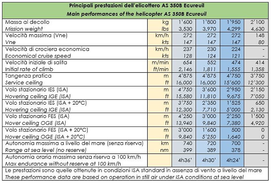
Performance
The table summarizes the main performances of the AS 350B Ecureuil:
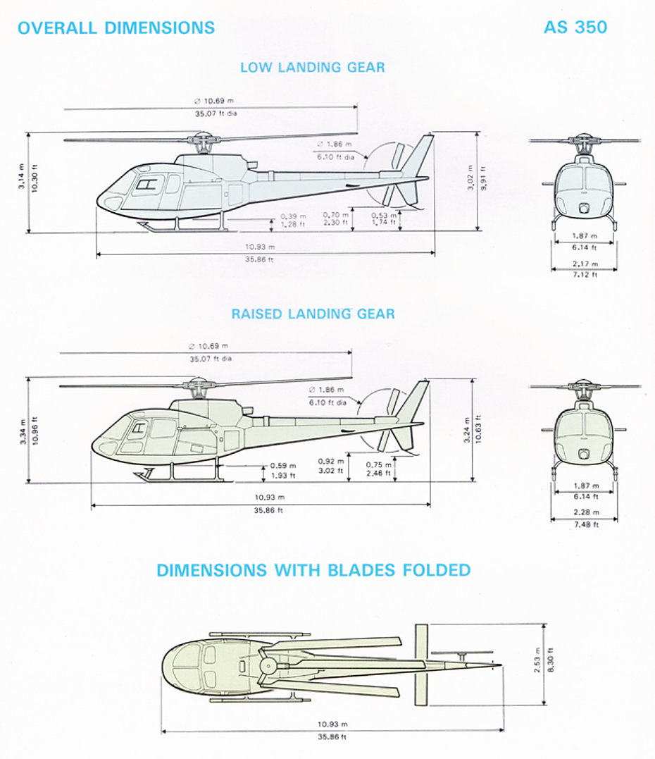
Weights and dimensions
The AS 350B Ecureuil has a standard empty weight of about 1,045 kg (2,303 lbs), while the MTOW with internal cargo is 1'950 kg (4,298 lbs), or 2'100 kg (4,629 lbs) with underslung load. The helicopter can lift a suspended load of about 650-700 kg (1,432-1,543 lbs).
The drawings show the external dimensions of the helicopter:
 with call-sign F-WZAL at Mollis/GL. This picture was probably taken during a demonstration tour late in 1977 or early 1978 (family Kolesnik)")
")
")
")
")
")
The AS 350B Ecureuil in Switzerland
In Switzerland towards the end of the 1970s the helicopter fleet was very heterogeneous, but in the field of air transportation the SA 315B Lama manufactured by Aérospatiale was the indisputed leader.
The main Swiss helicopter operators such as Air Zermatt, Air Glaciers, Bohag, Heliswiss, Eliticino and Air Grischa relied on this helicopter which had rapidly spread since 1971 for its qualities such as rusticity, reliability, sturdiness and the ability to lift a considerable suspended load.
However the Lama also had some weak points: for example the space in the cabin was rather limited, the consumption of kerosene was considerable and the cruising speed limited. Even the maintenance, due to the old mechanic, was quite demanding as well as expansive. At the end of the day rotor head, shaft and tail rotor required meticulous greasing.
The AS 350B Ecureuil could not compete with the SA 315B Lama in terms of lifting capacity. Unlike the Lama already with a suspended load of 650-700 kg, especially in summer in the Prealps, the AS 350B Ecureuil operated at its operational limits.
In service with the Linth Helikopter
Among the first Swiss operators to focus their interest on the AS 350B Ecureuil there was Linth Helikopter which in April 1979 received HB-XGW (s/n 1091 b/y 1979) affectionately christened “D'Fridolin” in homage to the monk Irish Saint Fridolin which is depicted on the banner of the Canton Glarus.
Until then the company had mainly used Hughes 269C and Agusta-Bell 206B Jet Ranger helicopters. The arrival of the new helicopter purchased at a cost of 730,000 Swiss Francs was a decisive step forward in the quality of the commercial services offered.
Just for the record it is interesting to remember that the Aérospatiale SA 315B Lama was introduced in Switzerland in 1971 at a price of 870'000 Swiss Francs, the equivalent of about 2'350'000 of today (2019).
")
The Ecureuil was much appreciated by the pilots for its great maneuverability and speed. Compared to the Jet Ranger the load capacity was greater as well as the volume in the cabin.
Air Grischa too was among the first operators in Switzerland to put in service the AS 350B Ecureuil. The first registered HB-XFY (s/n 1121 b/y 1979) entered service in August 1979 at the heliport of San Vittore/GR.
")
The SA 315B Lama and Ecureuil were complementary machines to each other. Appropriately employed by the coordination office, they were able to satisfy most of the customers' needs. The former was more suitable for heavy work at high altitude such as the supply of construction sites or logging, the second for the transportation of passengers and to supply alpine meadows and mountain huts.
Some AS 350B Ecureuil came into service with Helimission, a Swiss foundation that brings medical and spiritual help to people in remote and inaccessible areas. One of them with call-sign HB-XON (s/n 1104 b/y 1979 ex-I-LILL) had previously belonged to the famous Italian actor Bud Spencer.
")
")
Others AS350Bs were purchased by private operators.
Currently in the Swiss aircraft register only two aircraft of this type (HB-ZFA and HB-ZHO) are present. Both are mainly used for passenger transportation.
By the second mid of the 1980s operators started to replace their AS350Bs with the more powerful successor, the AS 350B1.
The AS 350B has the merit of having carried out an important work as a forerunner to the successive versions. Nowadays in fact in its most recent versions like the B3, B3+ and B3e the Ecureuil is the most used helicopter by Swiss helicopter operators.
Did you know that ...
The AS350/H-125 fleet has completed more than 26 million flight hours in total?
Airbus has announced that one of the AS 350s in service has logged over 37,600 flight hours?
Final note
For the preparation of the article, documentation older than forty years has been in part used. The author apologizes for any inaccuracies sometimes due to translation or interpretation mistakes or based on information that is no longer current.
Acknowledgments
The author express his gratitude to flight engineer Bernard Certain for the valuable help he provided to complete with historical information this article.
HAB 09/2019